
Adjusting Viewports
First off, you may want to maximize one of the "viewports" - the Top view showing in the upper-left when you first open 3dsmax. (This is so you can get a bigger view of what you're working on.) I'll select that view by clicking on it and then clicking the "Maximize Viewport Toggle" button as indicated:
_
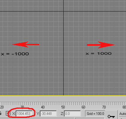
Next, you'll need to zoom out a bit. If I don't do this, I'll be working in too small an area and end up with a tiny track. I use the scrolling mouse button to zoom out until the darker gridlines that appear on either side of the black, center verticle-axis line are the ones that are 1000 units from that line. If they are only 100 units from the center, then I zoom out until a new set of dark lines comes into view.... and so on:
_
Creating a Loft (track surface)
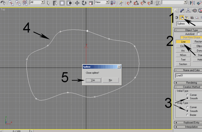
Follow steps 1 - 3. In step 4, plot out a line, using the left mouse button by laying down points. This may take some testing to figure out. If you need to try again, undo (ctrl-Z) and plot the points again. When/if you want to make a closed circuit and want to close it, click on the beginning point of your line. You're asked if you want to close the line (step 5). Select Yes.
_
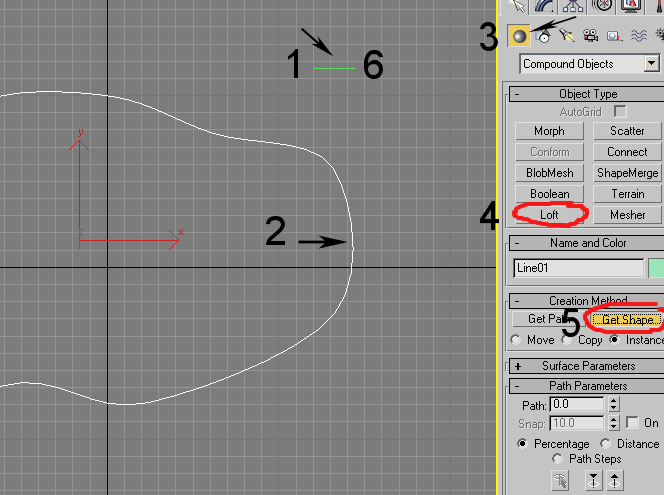
Now we'll create a loft from the line. But first, we need to create a "shape" line that will make up the cross section of our loft. The length of this second line should be same as the desired width of your track. Create this line with only 2 points - a beginning and end point (step 1). Right-click to stop placing points.
Now, select the first line - the "Path" (step 2). With the path line still selected, click the Compound Objects button (step 3) and then the Loft button (step 4). Now select the Get Shape button (step 5) and then click on the short - "shape" line you created (step 6). This makes a "loft" that follows the "path" line for its length and the "shape" line for its width.
_
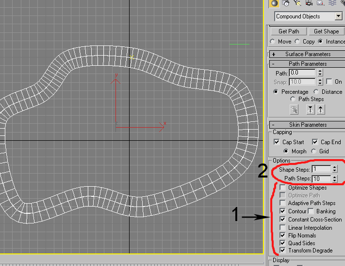
You should now see 2 new lines running along both sides of the "path" line. Check the boxes indicated in step 1 and deselect any that shouldn't be selected. (When you check the "flip normals" box, the shape steps suddenly appear in the loft, as shown in the picture.) Set shape steps to 1 and path steps to 10 (step 2). You will want to play with these later, as they affect how smooth the track feels when there are elevation changes and you're driving on it in the game.
_
Creating Infield Terrain
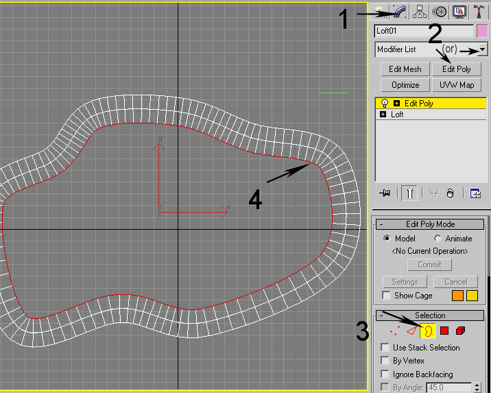
Step 1, select the Modify tab. From the Modifier List drop-down menu, select the Edit Poly modifier (step 2)... or if you've added a button for it already, click that. If using 3dsmax 3, click the "More..." button for the Modifier List.
---If using 3dsmax 3, you won't have the Edit Poly modifier. You can use the Edit Mesh modifier, but you'll probably find that it takes much longer to do the next step as Edit Mesh doesn't have a "Boundary" button so you'll have to use the "Edge" button. If using 3dsmax 3, click the "More..." button for the Modifier List.---
After adding the Edit Poly modifier, select the Boundary button (step 3). Use the mouse to select the inner boundary of the loft (step 4).
_
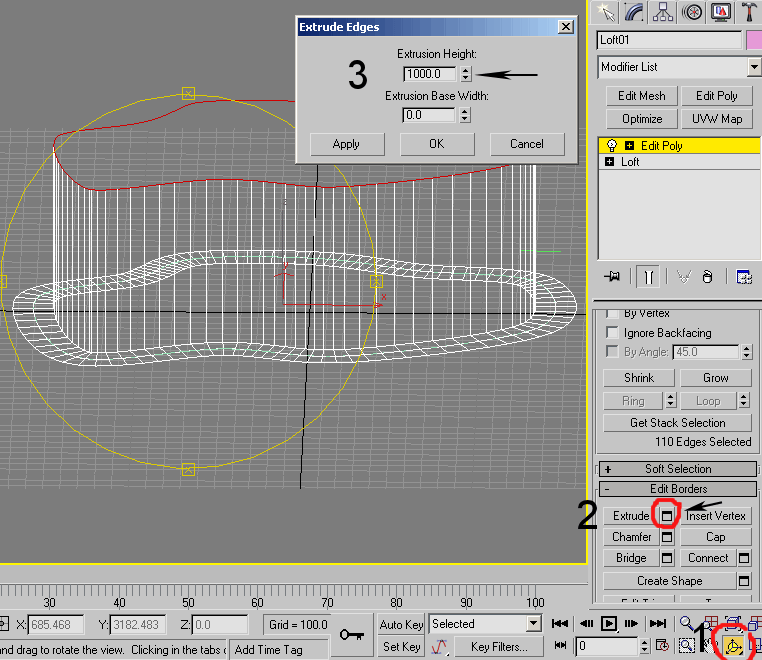
Step 1, select the Arc Rotate button. Clicking inside the the yellow circle that appears in the viewport, hold down the mouse button and drag. This rotates the view. Rotate until you can see the track from more of a side view. Now click the button next to Extrude as indicated (step 2). Increase the extrusion height to 1000 in the popup window and click OK (step 3).
_
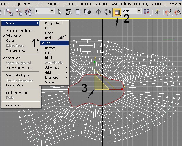
Now lets switch back to top view. You can rotate back or right-click "User" in the top-left corner of your viewport and select Views / Top from the drop-down list (step 1), after which you may need to zoom out a bit to get in full view of the track loft.
Be sure that the inner-loft boundary is still selected and click the Scale button (step 2). Place the mouse pointer over the yellow triangle and click/hold down and drag to shrink the extruded boundary so that it's not overlapping the edge of your track (loft) (step 3).
_
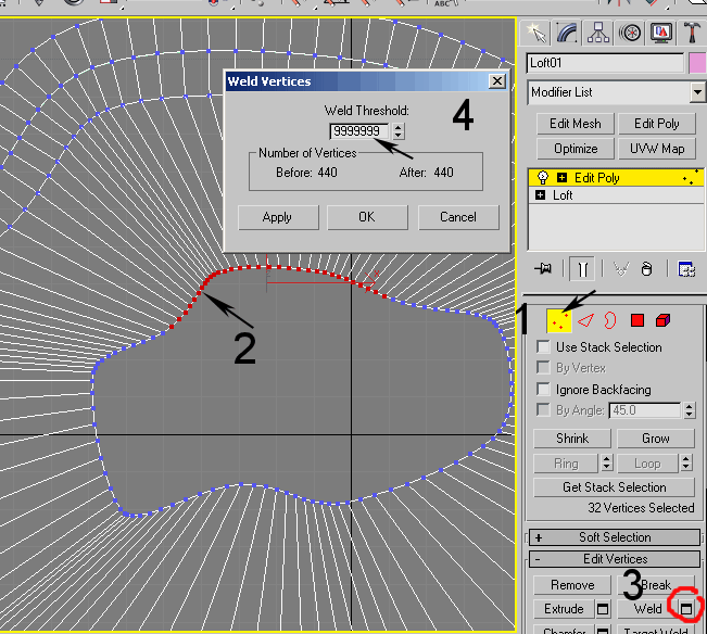
Step 1, select Vertices button. Step 2, I've selected a bunch of vertices along the inner edge of the extruded boundary, roughly a quarter, but more or less is fine. We want to weld these vertices together so select the button as indicated in step 3. In the popup, highlite the Weld Threshold box and type in 999999 or some big number so that all the selected vertices will be included in the weld (step 4). Click OK, and the vetices will become welded into one. Continue welding bunches of vertices until you've gone all the way around the inner edge.
_
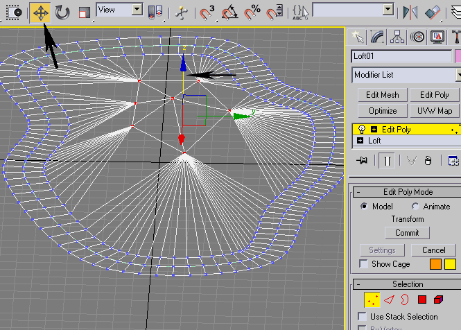
In the following picture, I've completed the previous steps and extruded the new inside edge one more time. This time, I've selected all of the vertices from the newly-extruded edge and welded them into one. Now the gap in the center is completely closed and I've effectively created a kind of spider web effect that will make up the infield terrain. Creating the outfield will be nearly the same process except that you'll be working outward.
Also, in this picture, I've selected all the infield vertices (but NOT the ones that are part of the edge of the original track loft) and moved them down by selecting the Move button and click-dragging the blue Z-axis arrow (shown below) to move those vertices downward. Individual vertices can be moved likewise to change the topography of the terrain.
_
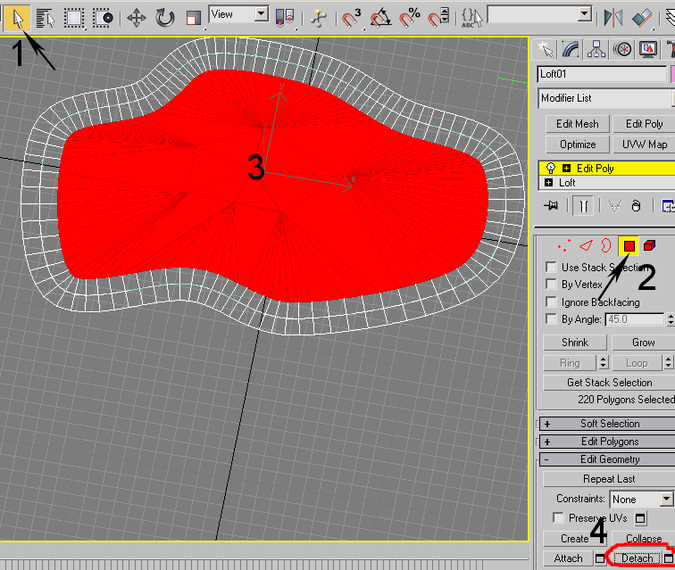
We can now detach the terrain from the track. Be sure the object you've created is selected. If you can't select it, click the arrow button as indicated in step 1. Select Polygon button (step 2). Drag a selection box over ONLY the polygons that make up your infield terrain - not the part that will be the track surface. If you miss some polygons, you can add-select/deselect a polygon by holding the Ctrl key and selecting the polygon. Click the Detach button (step 4), and the area of selected polygons will be detached and converted into a separate object.
_
Adding a Texture
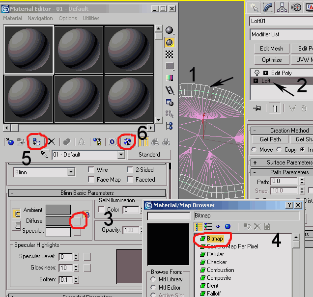
Step 1, make sure the track-object is selected. Select "Loft", as shown in step 2. Press the "M" key to bring up the Material Editor window and click the botton indicated in step 3. A new window pops up, double-click Bitmap and proceed to browse and open the texture you want to use for your track surface. Now click buttons as shown in steps 5 and 6.
_
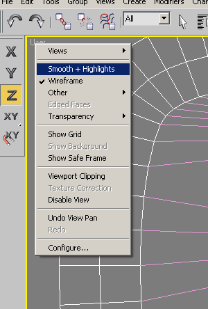
You've now assigned a texture to your track surface, but to see it you'll need to turn on "Smooth+Highlites" by rightclicking "User" or "Top" in the upper left of your viewport and selecting it from the drop-down menu. Now you should see some colors/textures.
_
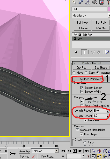
The track texture may be stretched out of purportion, so you'll need to check that "Loft" is selected again and put a check next to Apply Mapping, under Surface Parameters (step 1). You generally want to leave Width Repeat at 1, but try increasing the Length Repeat to see if it improves the look of your textured track surface.
_
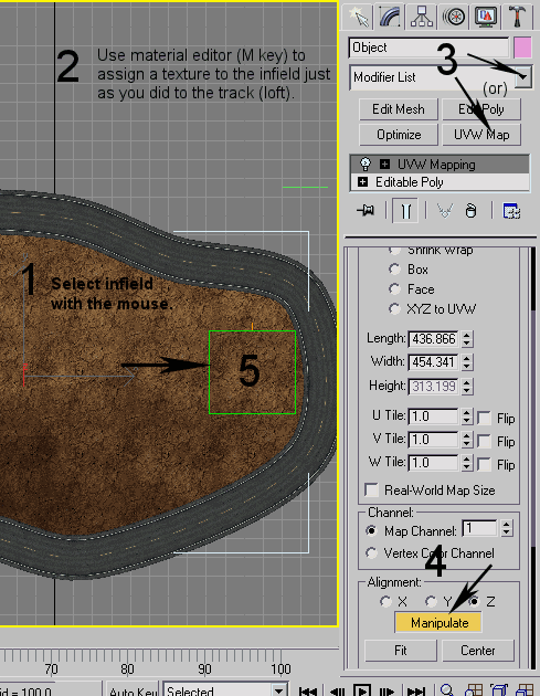
For the infield texture, select the infield (step 1) and follow the same steps to give a texture to it, using the Material Editor (step 2). However, we're going to "Apply Mapping" a little differently, so we'll do that now. Open the Modifier drop-down list and select the UVW Map modifier from the list (step 3). Now a yellow box appears, surrounding your infield terrain object. On the side pannel, scroll down to the Manipulate button and select it (step 4). The box turns green and you should be able to click/drag the edges of the box to make it smaller or larger, thus increasing or decreasing the resolution of the texture on your terrain.
by Charles
cnummelin@yahoo.com